
Combining the two classes We make machines not art by Darsha Hewitt and Tangible Programming - An Introduction by Johannes Deich I built a simple robot that is constantly fleeing the light.
I utilized what I learned about eletronic fundamentals and programming an Arduino-board, as well as 3D printing to put together this very first machine of mine.
Body

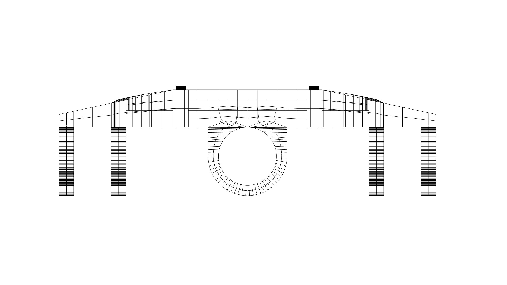

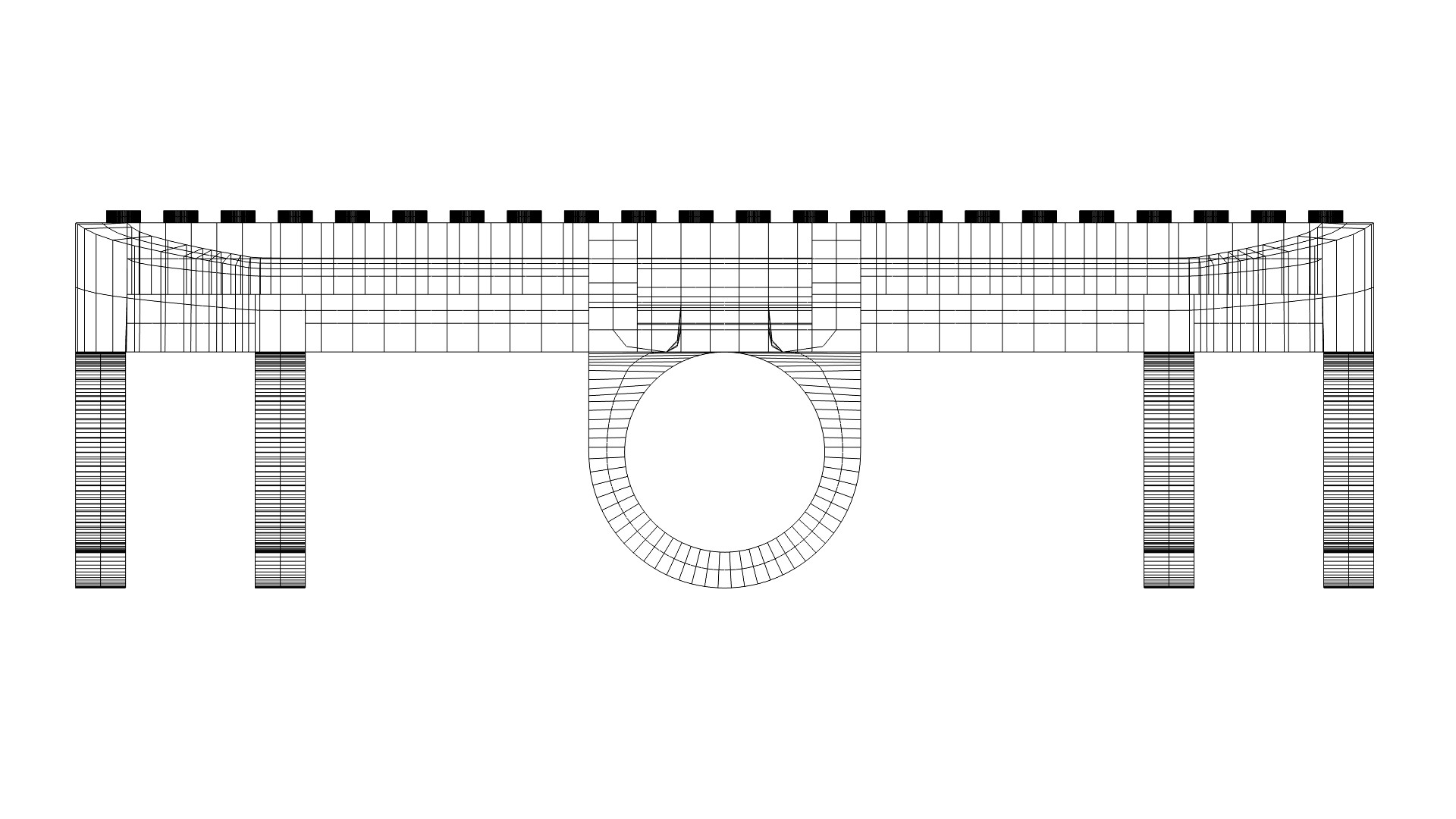

In order to have a reliable base to work on, I chose to model the body in a 3D environment and materialize it with the help of a 3D printer. It was my first fairly complex model to be printed and other than getting used to the printing process, I designed it to be as versatile as possible, keeping possible future robot projects in mind.

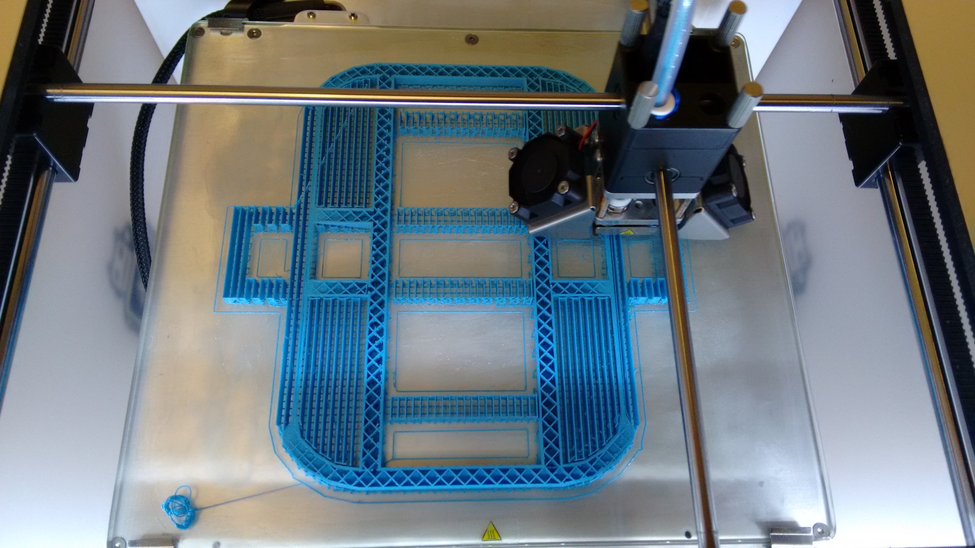


The model should provide a base for any bi-axial machine I may want to build, with enough space for a standard breadboard as well as some batteries. It’s holding the motors I obtained in place and allows them direct access to the ground. I chose to also add Lego compability to the model, in case I need to upgrade it with another board or other structures.
Wheels
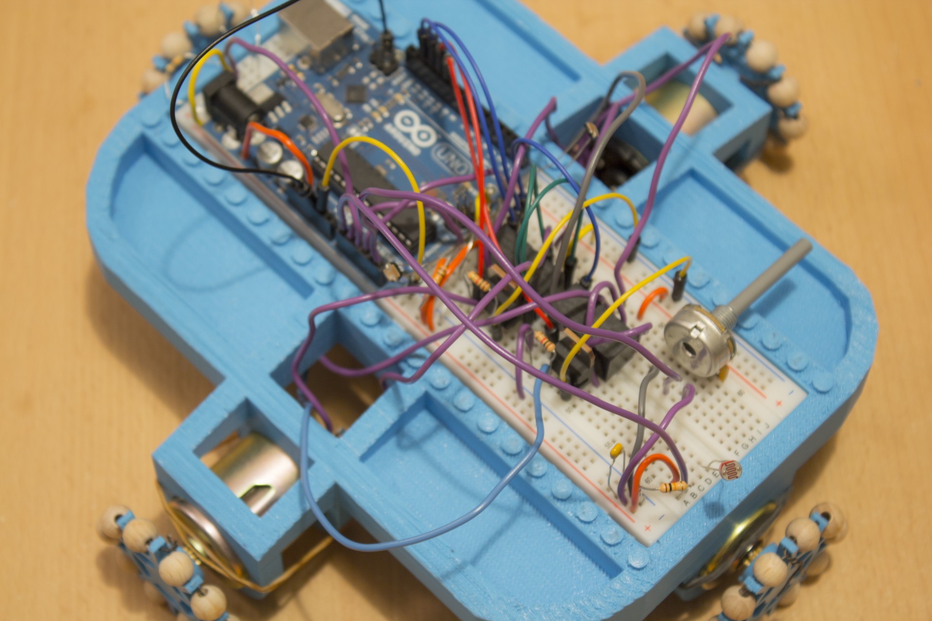
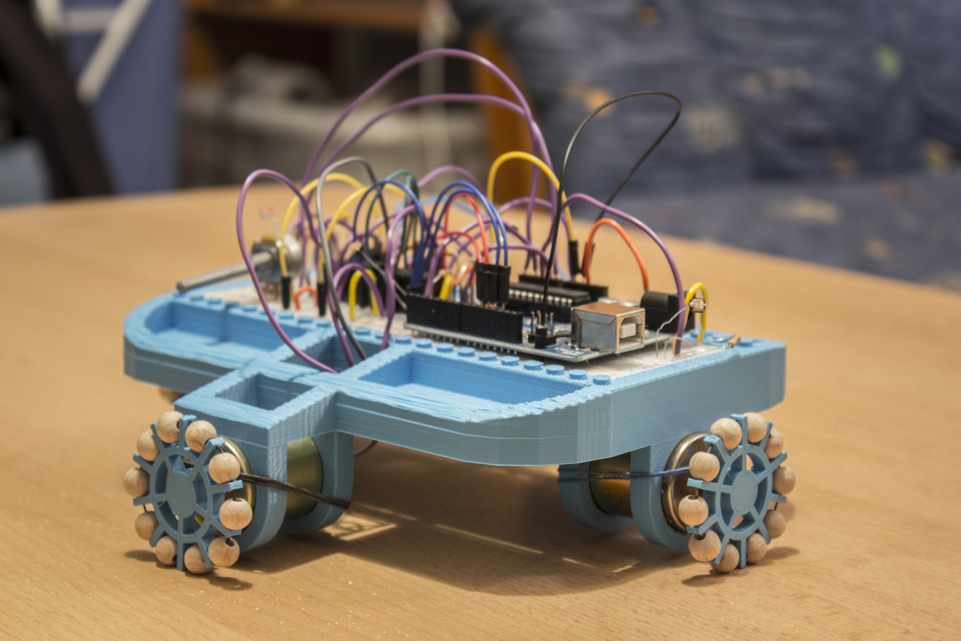
A movement apparatus containing steering would have been to complicated to control electronically, which is why I decided for bi-directional movement over orthogonal axes - via omni wheels. Omni wheels have small discs around their circumference, perpendicular to their turning direction, which allows them to be driven in their natural direction of turning while still being able to slide laterally.
After a few versions with teething problems I finally created a working design, making the printed wheels as small as possible. The Lateral movement is made possible by little wooden balls sitting on a wire.


Circuits

For the circuit concept I split the functions into basic modules: I need four photocells measuring light in each direction – therefore four inputs monitoring their resistance. I need two PWM driven outputs to control motor speed; one for each axis. The PWMs should each feed a transistor, enabling me to use an external power supply for the motors (they’re hungry for 12V). The motor’s direction will be switched by one relay per axis, changing their poles via a DPDT switch – giving me two more arduino outputs needed. Last but not least: A simple potentiometer, to manually set a resistance which can be compared to the photo resistors. This way, I can adjust my robot to the current light situation of the room.


Code
The code is very simple: It utilizes inputs from the circuit, compares them, calculates the speeds and triggers the respective outputs for directions and PWM.
The finished machine
The next (and probably last) step is to find a portable power supply that allows fully unplugged movement. Once the robot is wireless and mobile I can start experimenting with infinite inputs to control it instead of light.
Before I started working with the Arduino, the robot prototype worked with purely analogue electronics. Here's an early demonstration of it (in the video you can also see one of the first omni wheel designs which was way too big, making it impossible for the robot to move):
View full documentation for 'We make machines not art' class View full documentation for 'Tangible Programming' class